


Mitscherlich-type single-circle reflecting goniometer
Datecirca 1860
Inventory Number2002
ClassificationGoniometer
Subject
Maker
Johann August Oertling
1803 - 1866
User
Josiah P. Cooke
1827 - 1894
User
Wolcott Gibbs Memorial Laboratory, Harvard University
?
1911 - 2000
Cultural Region
Place of Origin
Place of Use
Dimensions26.5 x 26 x 30.5 cm (10 7/16 x 10 1/4 x 12 in.)
Circle: 15.5 cm (6 1/8 in.)
Circle: 15.5 cm (6 1/8 in.)
Material
DescriptionLarge brass Mitscherlich-type single-circle reflecting goniometer, Oertling No. 1326, no case. The instrument is made of a large vertical disc with 360 degrees scale rotating around a horizontal axis with two verniers mounted on the circumference is supported by a cone shaped column with the base on a flat tripod with leveling screws.
The crystal holder is mounted on two cross slides positioned at right angles, one on top of the other, that can be moved by rotating the adjustment knobs. On top of these flat traverses boxes are located two segmented cradles superimposed at right angles which can be used to tilt the crystal mount in an arc from the vertical to the horizontal. Using these traverse and tilt movements the edge of the crystal may be precisely aligned parallel with the axis of the disk. This mechanism (also called the "goniometer head") is essential for high precision measurements.
A signal and an observation scope are fixed on the tripod base in front of the crystal. The signal scope is a collimating tube with a rectangular slit mounted on top that produces parallel light. The disk can be finely or coarsely rotated using various knobs. The angles can be measured using the observation telescope to read the position of the vernier.
The crystal holder is mounted on two cross slides positioned at right angles, one on top of the other, that can be moved by rotating the adjustment knobs. On top of these flat traverses boxes are located two segmented cradles superimposed at right angles which can be used to tilt the crystal mount in an arc from the vertical to the horizontal. Using these traverse and tilt movements the edge of the crystal may be precisely aligned parallel with the axis of the disk. This mechanism (also called the "goniometer head") is essential for high precision measurements.
A signal and an observation scope are fixed on the tripod base in front of the crystal. The signal scope is a collimating tube with a rectangular slit mounted on top that produces parallel light. The disk can be finely or coarsely rotated using various knobs. The angles can be measured using the observation telescope to read the position of the vernier.
SignedEngraved on the degree plate: No. 1326 / Aug. Oertling / in Berlin
Curatorial RemarksMarked on tag: "This reflecting goniometer belonged to J. P. Cooke"; and on other side: "(probably will become) / Property of the / Wolcott Gibbs / Memorial Laboratory / Harvard University"
For a similar model see 2007a.
FunctionThe purpose of crystallographic goniometry is to measure the interfacial angles of crystals to determine their type. Single-circle measurement methods determine directly the angle between two crystal faces. It can also be used to determine the refractive index of a crystal by measuring the angles that light makes when crossing through it.
The goniometer is an assemblage that works by being able to hold and rotate a small crystal by any angle, and accurately measure these rotations. The crystal would be affixed (usually by wax) to the holder with the edge precisely aligned parallel with the axis of the disk. The axes of both the signal and the observation telescopes form a plane parallel to that of the disk. Since the lens system significantly reduces the reflection on the crystal, the signal telescope can be illuminated by a lamp placed behind it. The objective of the collimator is directed to the crystal edge. The crystal is rotated until the light reflected by the crystal face is seen in the observation telescope as a narrow strip of light. One would write down the angles at which this occurred, and then rotate the vertical disk until the next crystal face (across the edge) reflected the collimated light in exactly the same way. Writing down these new measurements and subtracting the first ones, one would get the exact supplementary angle between the two crystal faces (the real internal angle between the two faces totals 180 degrees minus the supplementary angle). This process would be continued and one could even use the system to measure the angles of the other crystal edges by using combinations of movements of the vertical and horizontal wheels and using more complex mathematical formulas to deduce the angles.
The goniometer is an assemblage that works by being able to hold and rotate a small crystal by any angle, and accurately measure these rotations. The crystal would be affixed (usually by wax) to the holder with the edge precisely aligned parallel with the axis of the disk. The axes of both the signal and the observation telescopes form a plane parallel to that of the disk. Since the lens system significantly reduces the reflection on the crystal, the signal telescope can be illuminated by a lamp placed behind it. The objective of the collimator is directed to the crystal edge. The crystal is rotated until the light reflected by the crystal face is seen in the observation telescope as a narrow strip of light. One would write down the angles at which this occurred, and then rotate the vertical disk until the next crystal face (across the edge) reflected the collimated light in exactly the same way. Writing down these new measurements and subtracting the first ones, one would get the exact supplementary angle between the two crystal faces (the real internal angle between the two faces totals 180 degrees minus the supplementary angle). This process would be continued and one could even use the system to measure the angles of the other crystal edges by using combinations of movements of the vertical and horizontal wheels and using more complex mathematical formulas to deduce the angles.
ProvenanceFrom Mineralogy - Geology Dept, 9/10/63; Mallinckrodt Chemical Laboratory, Harvard University, 1954.
Historical AttributesUsed by Josiah Parsons Cooke.

Johann August Oertling
Date: circa 1860
Accessories: box of crystal holders (2007b)
Object number: 2007a


Rudolf Fuess
Date: circa 1900
Object number: 1997-1-1731

Rudolf Fuess
Date: circa 1900
Accessories: wooden case; xeroxed article from Crystallography, N. Story-Maskelyne, Oxford 1898, p. 394-399, [The morphology of crystals] (describes in detail the use of the instrument); Stereo photograph of some experimental arrangement, perhaps a spectrometer; Spectrum photograph of Fluorit, signed "Victor Schumann, Leipzig 1901"
Object number: 1997-1-1752


W. Watson & Sons Ltd.
Date: circa 1885
Accessories: oculars (2 pairs): B and D; objectives in marked canisters (4): 1/4, 1/2, 1, 3 inches; condenser with iris diaphragm; rotating wheel diaphragm; iris diaphragm; set of 4 disk diaphragms in brass box; triple nosepiece; live box; prisms for Wenham binocular system (2); stage for simple microscope with rotating wheel diaphragm; vulcanite stage; spare knobs (2); parts box; case
Object number: 1249
Carl Zeiss, Optische Werkstätte, Jena
Date: circa 1902
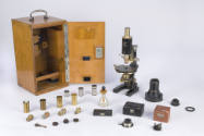
Accessories: oculars (5); objectives (5); microplanar objectives (2); iris diaphragm; abbe condenser; collars and sleeves for photography; parts box; Leitz object micrometer (1308b); cardioid condenser (1308d); immersion oil bottle (1308c) ; Leitz erecting prism (1308e); standing case with key
Object number: 1308a

Carl Zeiss Jena
Date: circa 1910
Accessories: ocular: K 20x ; objectives (3): Zeiss 2 mm HI, Zeiss 40 apochromat, B&L 10x apochromat; Abbe condenser; iris diaphragm; standing case
Object number: 1365

Martin J. Buerger
Date: 1945-1960
Object number: 1998-1-1673a


Johann August Oertling
Date: circa 1860
Accessories: box lid; tweezers; came with goniometer #2007a.
Object number: 2007b
See also/See also
