


Stirling hot air engine
Datecirca 1976
Inventory NumberDW1978
ClassificationHot Air Engine
Subject
Maker
ECO Motor Industries Ltd.
fl. 1970s - 1980s
Cultural Region
Place of Origin
Dimensions9.3 × 21.4 × 10.3 cm (3 11/16 × 8 7/16 × 4 1/16 in.)
box: 9.9 × 23.6 × 11.5 cm (3 7/8 × 9 5/16 × 4 1/2 in.)
box: 9.9 × 23.6 × 11.5 cm (3 7/8 × 9 5/16 × 4 1/2 in.)
Material
Accessoriesbox; brochure of <i>Stirling Hot Air Engine</i>
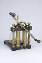
DescriptionA metal base painted orange supports on one side an aluminum cylinder that would contain the fuel used in warming the air that powers the working piston. On the other side is a gimbal circle (put inside a U-shaped rod) and the fly wheel that is rotated by the reciprocating motion of the piston. In the center, inside the finned cylinder, are the two pistons (working and displacer). The model is stored in the box. A sticker on box displays a number: "72223".
For more technical information on this engine, read the 1980 patent granted to this company. Though this later model is different, some parts are similar enough (the pistons chamber, for instance) to help better understand how this model works.
For more technical information on this engine, read the 1980 patent granted to this company. Though this later model is different, some parts are similar enough (the pistons chamber, for instance) to help better understand how this model works.
Signedon sticker, motor: ECO / MOTOR / GUELPH, ONTARIO / CANADA
on box: ECO MOTOR IND. LTD GUELPH, ONTARIO, CANADA
Curatorial RemarksThis engine's design is most likely earlier than the one described in a US patent granted in 1980, which can be seen <a href="http://www.google.com/patents?id=2Cc2AAAAEBAJ&printsec=abstract&zoom=4#PPA1,M1" target="_blank">here</a>.
FunctionThis is a hot air engine, which was intended to be powered by methylated spirits
put in the aluminum cylinder. The flame produce by the spirit would warm the air inside the tube, which would built pressure and push the working piston sideways. The latter would in part turn the gimballed circle, which would then turn the fly wheel. At the same time, it would push back the displacer piston towards the other side, providing cold air into the tube. This movement is repeated until there is no more hot air.
For more information, and a useful animation, go to the following website.
put in the aluminum cylinder. The flame produce by the spirit would warm the air inside the tube, which would built pressure and push the working piston sideways. The latter would in part turn the gimballed circle, which would then turn the fly wheel. At the same time, it would push back the displacer piston towards the other side, providing cold air into the tube. This movement is repeated until there is no more hot air.
For more information, and a useful animation, go to the following website.
ProvenanceDavid Wheatland, 1978. The inventory number DW1978 is likely to be the result of a misinterpretation of the year of acquisition on a tag.


Davies Charlton Ltd.
Date: circa 1960
Accessories: original cardboard box
Object number: DW0337


Louis Heinrici
Date: 1876-1920
Accessories: small can of Sterno canned heat cooling fuel
Object number: 1998-1-0080


Percy Williams Bridgman
Date: circa 1938
Accessories: one bolt protector; one attachment; two large bolts, black and white photographs (C6-G1). Parts can be found in drawer B11-I8. Bridgman Press Manual (copy) in instrument file folder
Object number: 1997-1-1819a



Percy Williams Bridgman
Date: 1924-1937
Accessories: cardboard box of spare parts; rubber tube; yellow hand pump; metal wire; torque wrench; wrenches (3); 1 CD; 1 audio cassette; 1 user's manual; 1 graph
Object number: 2004-1-0404
Percy Williams Bridgman
Date: 1924-1937
Object number: 2004-1-0404.1