


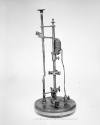
Hibbert's magnetic balance
Dateearly 20th Century
Inventory Number1997-1-0661
ClassificationElectric Balance
Subject
Inventor
Walter Hibbert
1852 - 1935
Cultural Region
Place of Origin
Dimensions21 × 32.5 × 14 cm (8 1/4 × 12 13/16 × 5 1/2 in.)
Material
Accessories7 accessory parts:
2 magnetic rods with spherical ends;
4 brass notches;
needle with tip inserted into cork;
DescriptionFulcrum, solenoid coil, and two rulers, one vertical, one horizontal, mounted on a rectangular wooden base supported by three legs in the form of screws that can be adjusted for leveling. The fulcrum consists of two pylons with holes at the top. A T-shaped brass clamp houses two needles at the end that are inserted into the pylons. The center, vertical bar of the clamp is in two parts connected by a screw. The top part contains a V-shaped notch that holds the iron magnet. The screw is adjusted so that the magnet is held firmly in place. A hole in the top of the clamp houses a needle which is kept separate and stuck in a cork in storage. The iron magnetic rod is a thin rod with spheres at either end. On one end is a strip of red paint.
Behind the fulcrum is a ruler, laid horizontally, fastened to the panel by two brass cylinders, and numbered in centimeters in both directions from zero at the point directly behind the fulcrum. Mounted on this ruler is a second scale to measure the deflection of the needle due to magnetic attraction or repulsion.
The solenoid consists of a short, wide wooden spool around which is wound fabric-insulated wire. To the left of the solenoid are two brass terminals onto which two nuts are screwed.
To the right of the solenoid is a second ruler, this one vertical, fastened at the top and bottom by two screws onto a varnished wood backing that is connected to the platform. Also fastened by those screws is a black metal piece holding a brass screw. The screw is threaded into a sliding square piece with a slot for a second magnetic rod in the same shape as the first. When the screw is turned, the square moves along the ruler. The ruler itself is numbered with the zero located at the level of the magnetic rod in the balance.
A hole in the left front corner is covered by a flat pear-shaped brass piece that pivots on a brass rivet.
Behind the fulcrum is a ruler, laid horizontally, fastened to the panel by two brass cylinders, and numbered in centimeters in both directions from zero at the point directly behind the fulcrum. Mounted on this ruler is a second scale to measure the deflection of the needle due to magnetic attraction or repulsion.
The solenoid consists of a short, wide wooden spool around which is wound fabric-insulated wire. To the left of the solenoid are two brass terminals onto which two nuts are screwed.
To the right of the solenoid is a second ruler, this one vertical, fastened at the top and bottom by two screws onto a varnished wood backing that is connected to the platform. Also fastened by those screws is a black metal piece holding a brass screw. The screw is threaded into a sliding square piece with a slot for a second magnetic rod in the same shape as the first. When the screw is turned, the square moves along the ruler. The ruler itself is numbered with the zero located at the level of the magnetic rod in the balance.
A hole in the left front corner is covered by a flat pear-shaped brass piece that pivots on a brass rivet.
Signednot signed
FunctionThe balance was generally used for pedagogical purposes such as demonstrating the inverse square rule, comparing the pole strength of two magnets, measurement of the equatorial and axial fields of magnets, and measuring, in cgs units, the strengths of currents.
To accomplish the former, a rod is inserted into the sliding indicator on the vertical scale so that one of its poles is directly over a pole in the balance rod. The balance rod moves freely about a fulcrum, so the bar can be deflected in either direction depending on the attraction or repulsion between the poles of the two rods. The deflection of the rod is indicated by the needle. The vertical distance between the two poles can be adjusted by turning the screw that is connected to the sliding indicator on the vertical scale.
The current in the solenoid can be measured by measuring the deflection of the magnet due to the solenoid's magnetic field.
This is the "Royal Naval College Pattern" of the Hibbert magnetic balance, characterized by the two balls and the pointer.
To accomplish the former, a rod is inserted into the sliding indicator on the vertical scale so that one of its poles is directly over a pole in the balance rod. The balance rod moves freely about a fulcrum, so the bar can be deflected in either direction depending on the attraction or repulsion between the poles of the two rods. The deflection of the rod is indicated by the needle. The vertical distance between the two poles can be adjusted by turning the screw that is connected to the sliding indicator on the vertical scale.
The current in the solenoid can be measured by measuring the deflection of the magnet due to the solenoid's magnetic field.
This is the "Royal Naval College Pattern" of the Hibbert magnetic balance, characterized by the two balls and the pointer.

W.G. Pye & Company, Ltd.
Date: circa 1920
Accessories: 5 accessory parts:
2 magnetic rods with spherical ends;
one brass notch;
needle with tip inserted into cork;
Object number: 1997-1-0662


F. F. Metzger
Date: 1905-1930
Accessories: steel contact points (4);
strain gauges (2);
square bars (2);
dial gauge
Object number: 1999-1-0083
Department of Physics, Harvard University
Date: mid 19th-late 19th Century
Object number: 0166

F. F. Metzger
Date: early 20th Century
Accessories: brown leatherbound wood case with purple stuffed velvet lining two metal locks in front;
steel rod contact points (4);
metal bar;
strain gauge;
card describing gauge ratio
Object number: 1999-1-0084

F. F. Metzger
Date: circa 1927
Accessories: wooden box lined with velvet cushioning;
strain gauge;
iron bar;
steel rod contact points (2);
nails (3) wrapped in paper;
manual;
single stationery paper;
pamphlet (price list)
Object number: 1999-1-0065

Ducretet et Lejeune
Date: 1892-1896
Object number: DW0089


Jean-Gabriel-Auguste Chevallier
Date: 1830-1848
Accessories: cork-like wooden object; wooden case
2 wooden "fins" (possibly part of case)
4 mounting screws
1 small brass mounting object
1 brass key-like object
Object number: 1998-1-1248

Keuffel & Esser Company
Date: 1916-1926
Accessories: wood case and key; photocopy of original Keuffel & Esser Co. catalogue in which the model is introduced
Object number: 1996-1-0084


Carl Zeiss Jena
Date: circa 1926
Accessories: wooden box with two hook-and-eye latches to fasten front opening; in instrument file: instruction book (photocopy); Geissler tube labeled "H2"; carboard tube containing German thermometer C in stainless steel holder that screws into instrument; glass bottle with cork stopper labeled "Monobromnaphthalin, Germany nD=1 658"; small round cardboard box labeled "For Pulfrich Refractometer" containing one tubulure
Object number: 1996-1-0229