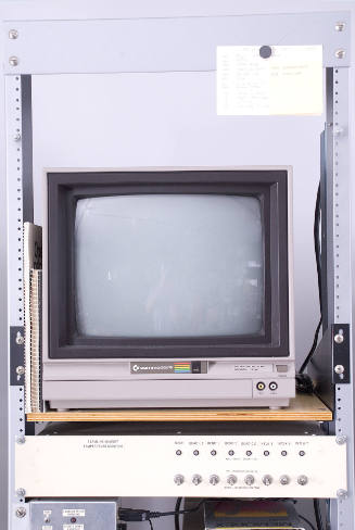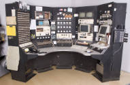


control console from Harvard Cyclotron Laboratory
Date1947-2002
Inventory Number2003-1-0291
ClassificationControl Console
Maker
Harvard Cyclotron Laboratory
1937 - 2002
Maker
Bernard Gottschalk
1935 - 2021
Maker
Miles Wagner
Maker
Kenneth T. Bainbridge
1904 - 1996
Maker
Andreas Koehler
1930 - 2015
User
Ethan W. Cascio
born 1960
Associate Name
Raymond Nathaniel Kjellberg
1925 - 1993
User
Janet M. Sisterson
born 1940
Maker
Ortec
1960-present
Maker
Tektronix, Inc.
1946-present
Maker
Keithley Instruments Inc.
1946-present
Maker
Simpson Electric Company
founded 1934
Maker
Weston Electrical Instrument Corporation
founded 1888
Maker
Westinghouse Electric Corporation
1945 - 1997
Maker
Triplett
founded 1904
Maker
Digital Equipment Corporation
1957 - 1998
Maker
Durant Manufacturing Company
fl. 1916 - 1950s
Maker
Apple Computer Inc.
1976-present
Maker
Talkaphone
founded 1935
Cultural Region
Place of Origin
Material
DescriptionFive steel racks of instruments are bolted together in a curve with a formica tabletop in front. Each rack has multiple instruments, some from the late 1940s when the control console was first assembled and others that were swapped in later by technicians. Various users added cartoons, poems, and stickers.
Going from left to right, and top to bottom, the components of the console are as follows (numbers refer to the keyed diagram):
Left Side of Rack A
1. Schematic of the cyclotron lab.
2. Clipboard for notes.
3. Mechanical pencil sharpener (by Boston).
4. Rack for patients' files sorted by “Large field,” “Retina,” and “Neurosurgical.”
[not shown] On the extended metal housing that walled off the electrical cables behind the console, there was a bulletin board with a staff phone directory, instructions for emergencies, and takeout menus for pizza and Chinese food. The bulletin board is preserved as inv. no. 2003-1-0309.
Rack A
1. Photograph of Dr. Ray Kjellberg and physicist Andreas Koehler in the Bio-Medical Annex of the Harvard Cyclotron Lab, circa 1980s.
2. Pogo cartoon.
3. Trouble lights. 115 volt AC, incandenscant bulbs. Red signaled something that was keeping the cyclotron from working.
4. Control circuitry interfacing to a computer. This board was built by physicist Bernard Gottschalk.
5. Toggle switches to turn on the magnet, power supplies, etc.
6. [on counter] Telephone (AT&T supplied by NYNEX )
Connector AB
7. HCL staff directory and telephone list.
8. Pencil cup made from a proton beam range compensator (also known as a bolus).
Rack B
1. Poem written and posted by Kristen Johnston, long-time HCL staff member, upon learning that the Harvard Cyclotron might be decommissioned:
Remember…
I wasn’t the best because
I was the oldest,
I was the oldest because
I was the best.
2. Small box of cards to keep track of beam runs for patient treatment or experiment.
3. Power-line monitor (RCA) for the regular line voltage (120 volts) delivered to the property. A dip in the power caused a problem for the cyclotron. A Star Wars figure of Jar Jar Binks with his mouth taped shut sits on top of the monitor.
4. NIM crate with Ortec counters, which was not for routine use of the cyclotron. It was for physicist Janet Sisterson's measurements of nuclear cross-sections.
5. Oscilloscope (Tektronix) with two channels—one for the radio frequency oscillator, and the other for the ion source pulse.
6. Current integrator, which read the current from a small ionization chamber using a Keithley electrometer. The amount of current was proportional to the total dose of radiation. Alongside this instrument is a switch selecting between different detectors.
7. Switch to electromagnets. "Quad" refers to quadrupole magnets that were used to focus the beam. Next to this is a schematic diagram of the system. This component was built by Bernard Gottschalk.
8. Milliameter (Simpson) labeled “EXTERNAL BEAM.” This was a safety item that showed technicians whether the proton beam was on or off in any treatment room.
9. Five meters in a row: Four show the ion source position—up/down, in/out, clockwise/counterclockwise, and left/right. The last one is a spare meter. The meters are labeled either microamperes or galvanometer, and were made by Simpson.
10. Toggle switches: The 4 black ones go to motors that correspond to the meters above. The 4 orange ones go to select the beams used.
Connector BC
11. Two DC meters by Boonton Electronics Corp. The top one read background radiation in the cyclotron vault, thereby giving a rough idea of how much beam was being produced inside the cyclotron. The bottom Boonton meter measured the external beam at the beam block. The ratio of the top reading to that on the bottom—i.e., of the internal beam to the external beam—gave an idea of how efficient the beam transport out to the beam block was.
12. Note pad.
Rack C
1. Beam clipper to control low-beam intensity. From right to left, it has a coarse control, a fine control, and a Simpson meter. The wooden sign, "BEAM Clipper OUT" (and on its reverse side, “BEAM Clipper IN”), let users know if the carbon clipper was in or out. The sign was made by Ethan W. Cascio, accelerator engineer and HCL operations manager, one morning when he was mystified why he couldn’t get any beam out.
2. Bank of 20 meters, 5 per row, made by various makers including Simpson, Westinghouse, Weston, and Triplett. From left to right, they measure:
row 1: filament volts (a replacement old meter)
filament current (a replacement old meter)
voltage across the main magnet
current through the main magnet
[disconnected meter]
row 2: oscillator filament primary current
[disconnected meter]
ion source filament primary current
arc current
magnet hours running time
row 3: Dee bias volts
grid bias volts--i.e., voltage on grid of the main oscillator
plate RF current
cathode RF current
“Rot. C. Mesh”--rotating condenser mesh current
row 4: Dee bias current
oscillator plate volts
oscillator plate current
Dee RF volts. This is voltage to accelerate the protons. Very Important!
“Rot. C. Rate”—rotating condenser rate
3. Ion source pulse--another circuit built by Bernard Gottschalk. It kicked in protons at the beginning of the acceleration cycle.
4. Toggle switches for instruments controlling the number of protons per second, ion source, oscillator, and control console used. By row, from left to right:
row 1: rotating condenser rate, which determines the number of protons per second
oscillator volts adjustment
ion source filament adjustment
ion source gas adjustment
row 2: bending magnets
rotating condenser
dee bias
oscillator plate volts
ion source filament volts
ion source gas
ion source pulse
oscillator control special, which switched the control from this
console to the other console in the Cyclotron Lab
tune
standby
Connector CD
5. Hewlett Packard RPN scientific calculator.
6. Fortune cookie inserts. The one on top reads, “Because of your melodic nature, the moonlight never misses an appointment.” The lower one reads, “A pleasant experience is ahead; don’t pass it by.” A technician has penned before and after this fortune, “Cyclotron’s Future:-- / Sun. 2 June 2002.”
Rack D
1. Area video monitors (Panasonic). They were closed-circuit TVs showing patient treatment rooms.
2. Safety circuit built by Miles Wagner, Director of HCL, for setting up absorbers (aka range shifters). The absorbers are labeled in water equivalent depth attenuation. A thumb-wheel switch sets up a stack of absorbers. The display should equal the setting when the system is good to go. Warning lights show a fault in the patient set-up, which will prevent the machine from running. There are buttons to override the interlock.
3. Control for 4 different scattering systems for 4 different field sizes in patient treatment room no. 2. These scatter the protons as needed to spread out the field of the beam in order to cover the patient's tumor. A selector switch points to contoured, retino, large, or small.
4a. Computer monitor hooked up to VAX computer. The monitor is made by Digital.
4b. [on counter below] Computer keyboard hooked up to VAX computer. Also by Digital.
5. Circuit that terminated treatment in room no. 2. Channel 1 is a pulse counter. It has a meter labeled “CHANNEL 1 COUNT RATE” and “BEAM 2.” Channel 2 is a backup counter.
6. Beam turn-off. The technician would dial in the number of monitor units using the Durant switch. When this number was reached, the beam would turn off.
7. Toggle switches to control magnets and beam shutter, which stopped the beam from entering the treatment room.
Connector DE
8. A good-luck charm from Japan. It came from an MGH physicist, Ken Gall, who bought it when attending a proton-therapy conference in Japan. The charm was originally labeled, “Cures Cancer.”
9. Miscellaneous circuit diagrams and instructions, including one for the “Cyclotron Vacuum System.”
Rack E
1. Diagnostic display of the vacuum system (circa 1948), with a meter, thermocouple, and calibration chart. The white rectangle in the diagram refers to the cyclotron tank.
2. Modern vacuum ionization gauge (Varian) used to monitor the level of vacuum in the cyclotron. If the vacuum level was bad, it could indicate a leak.
3a. Apple computer monitor and CPU (Macintosh IIsi) for experiments and data analysis. Tucked next to this are some clipboards and a 2002 issue of the magazine Discover.
3b. [on counter below] Computer keyboard and mouse for the Macintosh IIsi.
4. Neutron monitors with four scalers. This system was built by Bernard Gottschalk.
Right Side of Rack E
1. Electric pencil sharpener (by Boston)
2. Intercom marked “TALK-A-PHONE.”
Going from left to right, and top to bottom, the components of the console are as follows (numbers refer to the keyed diagram):
Left Side of Rack A
1. Schematic of the cyclotron lab.
2. Clipboard for notes.
3. Mechanical pencil sharpener (by Boston).
4. Rack for patients' files sorted by “Large field,” “Retina,” and “Neurosurgical.”
[not shown] On the extended metal housing that walled off the electrical cables behind the console, there was a bulletin board with a staff phone directory, instructions for emergencies, and takeout menus for pizza and Chinese food. The bulletin board is preserved as inv. no. 2003-1-0309.
Rack A
1. Photograph of Dr. Ray Kjellberg and physicist Andreas Koehler in the Bio-Medical Annex of the Harvard Cyclotron Lab, circa 1980s.
2. Pogo cartoon.
3. Trouble lights. 115 volt AC, incandenscant bulbs. Red signaled something that was keeping the cyclotron from working.
4. Control circuitry interfacing to a computer. This board was built by physicist Bernard Gottschalk.
5. Toggle switches to turn on the magnet, power supplies, etc.
6. [on counter] Telephone (AT&T supplied by NYNEX )
Connector AB
7. HCL staff directory and telephone list.
8. Pencil cup made from a proton beam range compensator (also known as a bolus).
Rack B
1. Poem written and posted by Kristen Johnston, long-time HCL staff member, upon learning that the Harvard Cyclotron might be decommissioned:
Remember…
I wasn’t the best because
I was the oldest,
I was the oldest because
I was the best.
2. Small box of cards to keep track of beam runs for patient treatment or experiment.
3. Power-line monitor (RCA) for the regular line voltage (120 volts) delivered to the property. A dip in the power caused a problem for the cyclotron. A Star Wars figure of Jar Jar Binks with his mouth taped shut sits on top of the monitor.
4. NIM crate with Ortec counters, which was not for routine use of the cyclotron. It was for physicist Janet Sisterson's measurements of nuclear cross-sections.
5. Oscilloscope (Tektronix) with two channels—one for the radio frequency oscillator, and the other for the ion source pulse.
6. Current integrator, which read the current from a small ionization chamber using a Keithley electrometer. The amount of current was proportional to the total dose of radiation. Alongside this instrument is a switch selecting between different detectors.
7. Switch to electromagnets. "Quad" refers to quadrupole magnets that were used to focus the beam. Next to this is a schematic diagram of the system. This component was built by Bernard Gottschalk.
8. Milliameter (Simpson) labeled “EXTERNAL BEAM.” This was a safety item that showed technicians whether the proton beam was on or off in any treatment room.
9. Five meters in a row: Four show the ion source position—up/down, in/out, clockwise/counterclockwise, and left/right. The last one is a spare meter. The meters are labeled either microamperes or galvanometer, and were made by Simpson.
10. Toggle switches: The 4 black ones go to motors that correspond to the meters above. The 4 orange ones go to select the beams used.
Connector BC
11. Two DC meters by Boonton Electronics Corp. The top one read background radiation in the cyclotron vault, thereby giving a rough idea of how much beam was being produced inside the cyclotron. The bottom Boonton meter measured the external beam at the beam block. The ratio of the top reading to that on the bottom—i.e., of the internal beam to the external beam—gave an idea of how efficient the beam transport out to the beam block was.
12. Note pad.
Rack C
1. Beam clipper to control low-beam intensity. From right to left, it has a coarse control, a fine control, and a Simpson meter. The wooden sign, "BEAM Clipper OUT" (and on its reverse side, “BEAM Clipper IN”), let users know if the carbon clipper was in or out. The sign was made by Ethan W. Cascio, accelerator engineer and HCL operations manager, one morning when he was mystified why he couldn’t get any beam out.
2. Bank of 20 meters, 5 per row, made by various makers including Simpson, Westinghouse, Weston, and Triplett. From left to right, they measure:
row 1: filament volts (a replacement old meter)
filament current (a replacement old meter)
voltage across the main magnet
current through the main magnet
[disconnected meter]
row 2: oscillator filament primary current
[disconnected meter]
ion source filament primary current
arc current
magnet hours running time
row 3: Dee bias volts
grid bias volts--i.e., voltage on grid of the main oscillator
plate RF current
cathode RF current
“Rot. C. Mesh”--rotating condenser mesh current
row 4: Dee bias current
oscillator plate volts
oscillator plate current
Dee RF volts. This is voltage to accelerate the protons. Very Important!
“Rot. C. Rate”—rotating condenser rate
3. Ion source pulse--another circuit built by Bernard Gottschalk. It kicked in protons at the beginning of the acceleration cycle.
4. Toggle switches for instruments controlling the number of protons per second, ion source, oscillator, and control console used. By row, from left to right:
row 1: rotating condenser rate, which determines the number of protons per second
oscillator volts adjustment
ion source filament adjustment
ion source gas adjustment
row 2: bending magnets
rotating condenser
dee bias
oscillator plate volts
ion source filament volts
ion source gas
ion source pulse
oscillator control special, which switched the control from this
console to the other console in the Cyclotron Lab
tune
standby
Connector CD
5. Hewlett Packard RPN scientific calculator.
6. Fortune cookie inserts. The one on top reads, “Because of your melodic nature, the moonlight never misses an appointment.” The lower one reads, “A pleasant experience is ahead; don’t pass it by.” A technician has penned before and after this fortune, “Cyclotron’s Future:-- / Sun. 2 June 2002.”
Rack D
1. Area video monitors (Panasonic). They were closed-circuit TVs showing patient treatment rooms.
2. Safety circuit built by Miles Wagner, Director of HCL, for setting up absorbers (aka range shifters). The absorbers are labeled in water equivalent depth attenuation. A thumb-wheel switch sets up a stack of absorbers. The display should equal the setting when the system is good to go. Warning lights show a fault in the patient set-up, which will prevent the machine from running. There are buttons to override the interlock.
3. Control for 4 different scattering systems for 4 different field sizes in patient treatment room no. 2. These scatter the protons as needed to spread out the field of the beam in order to cover the patient's tumor. A selector switch points to contoured, retino, large, or small.
4a. Computer monitor hooked up to VAX computer. The monitor is made by Digital.
4b. [on counter below] Computer keyboard hooked up to VAX computer. Also by Digital.
5. Circuit that terminated treatment in room no. 2. Channel 1 is a pulse counter. It has a meter labeled “CHANNEL 1 COUNT RATE” and “BEAM 2.” Channel 2 is a backup counter.
6. Beam turn-off. The technician would dial in the number of monitor units using the Durant switch. When this number was reached, the beam would turn off.
7. Toggle switches to control magnets and beam shutter, which stopped the beam from entering the treatment room.
Connector DE
8. A good-luck charm from Japan. It came from an MGH physicist, Ken Gall, who bought it when attending a proton-therapy conference in Japan. The charm was originally labeled, “Cures Cancer.”
9. Miscellaneous circuit diagrams and instructions, including one for the “Cyclotron Vacuum System.”
Rack E
1. Diagnostic display of the vacuum system (circa 1948), with a meter, thermocouple, and calibration chart. The white rectangle in the diagram refers to the cyclotron tank.
2. Modern vacuum ionization gauge (Varian) used to monitor the level of vacuum in the cyclotron. If the vacuum level was bad, it could indicate a leak.
3a. Apple computer monitor and CPU (Macintosh IIsi) for experiments and data analysis. Tucked next to this are some clipboards and a 2002 issue of the magazine Discover.
3b. [on counter below] Computer keyboard and mouse for the Macintosh IIsi.
4. Neutron monitors with four scalers. This system was built by Bernard Gottschalk.
Right Side of Rack E
1. Electric pencil sharpener (by Boston)
2. Intercom marked “TALK-A-PHONE.”
In Collection(s)
Signedunsigned
Historical AttributesThis control console was used at the Harvard Cyclotron Laboratory beginning in 1948, and evolved over time to include the items currently on it.

Harvard Cyclotron Laboratory
Date: 1960-1980
Object number: 2003-1-0309

American
Date: 1960-1980
Accessories: commodore video monitor (2003-1-0239b); magnetic temperature monitor (2003-1-0239c); pulse timer (2003-1-0239d); Commodore computer, keyboard (2003-1-0239e); Panasonic dot-matrix printer (2003-1-0239f); two cyclotron lead bricks (2003-1-0239g, h); cardboard box with printer paper (2003-1-0239i)
Object number: 2003-1-0293a

Reynolds Metal Company
Date: circa 1960
Object number: 2003-1-0271


Sony Corporation
Date: dated 1998
Object number: 2003-1-0288


James White
Date: circa 1895
Accessories: wooden case with weights (0298b)
Object number: 0298a


Bernard Gottschalk
Date: circa 1965
Object number: 2003-1-0313

George Washington Pierce
Date: circa 1926
Accessories: 8 batteries (removed during FAE inventory).
Object number: RS1275