


variometer
Datecirca 1920
Inventory NumberRS0553
ClassificationVariometer
Subject
Maker
General Radio Company
1915-present
User
Cruft Laboratory, Harvard University
founded 1914
Cultural Region
Place of Origin
Place of Use
Dimensions20 x 18 x 19 cm (7 7/8 x 7 1/16 x 7 1/2 in.)
Material
DescriptionTwo coils, one mounted inside the other. The outer coil is in an upright square wooden frame, and it has a circular cavity in the middle where the inner coil is mounted with a wooden spool. Demonstration tuning coil mounted on square wooden base, coil mounted in square wooden frame. On one side is a large discoidal dial which turns the inside coil. It has a semicircular scale 0-100, corresponding to angles 0 to 180 degrees.
On its wooden base are four electrical connectors.
On its wooden base are four electrical connectors.
In Collection(s)
Signedetched on dial: GENERAL RADIO CO. / CAMBRIDGE, MASS.
Curatorial RemarksProbably an instructional version of a variometer, with all components clearly visible.
There are four very similar variometers in the collection: RS0466, RS0551, RS0552 and RS0553.
FunctionVariometers are a form of variable inductance that was popular as a tuning coil for radio circuits in the 1920s.
Tuning coils in general are used to alter the transmission or reception frequency of a circuit. The frequency is inversely proportional to the square root of a circuit's capacitance and inductance, so changing the circuit's inductance is a way to alter its transmission or reception frequency.
Variometers in particular consist of two coils, one inside the other. The internal coil can be rotated so that its axis can be parallel, perpendicular, or opposite (as well as intermediate settings) to the axis of the external coil. The current circulates first inside one coil, then the other. As a result, the inductance will the at a maximum when both coils are parallel, and at a minimum when they are in contrary directions. This allows the circuit's frequency to be varied within a range.
One of the advantages of variometers compared to other forms of tuning coil is that the total length of wire in the circuit remains the same, so its total resistance remains constant.
Tuning coils in general are used to alter the transmission or reception frequency of a circuit. The frequency is inversely proportional to the square root of a circuit's capacitance and inductance, so changing the circuit's inductance is a way to alter its transmission or reception frequency.
Variometers in particular consist of two coils, one inside the other. The internal coil can be rotated so that its axis can be parallel, perpendicular, or opposite (as well as intermediate settings) to the axis of the external coil. The current circulates first inside one coil, then the other. As a result, the inductance will the at a maximum when both coils are parallel, and at a minimum when they are in contrary directions. This allows the circuit's frequency to be varied within a range.
One of the advantages of variometers compared to other forms of tuning coil is that the total length of wire in the circuit remains the same, so its total resistance remains constant.
ProvenanceFrom the Cruft Laboratory, Harvard University.
Historical AttributesCruft


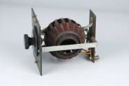
American Radio and Research Corporation
Date: circa 1921
Object number: 1998-1-0884

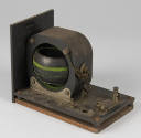
Hearwell Radio Company
Date: ca. 1915-1930
Object number: RS0780

Date: 1890-1930
Object number: RS0508

Date: late 19th-early 20th Century
Object number: RS0168


Sir Charles Wheatstone
Date: circa 1860
Accessories: part of a set that includes the transmitter (DW0887a)
Object number: DW0887b

Robert W. Paul Instrument Company
Object number: 2012-1-0013

Rudolph Koenig
Date: circa 1865
Object number: 1997-1-0892d
See also/See also


