


"inductometer" variometer
Datecirca 1920
Inventory NumberRS0083
ClassificationVariometer
Subject
Maker
Leeds & Northrup Company
1903 - 1995
User
Bowdoin College, Department of Physics
founded after 1794
Cultural Region
Place of Origin
Place of Use
Dimensions36 x 31 x 31 cm (14 3/16 x 12 3/16 x 12 3/16 in.)
Material
DescriptionLarge cylindrical wooden frame with discoidal panels on top and bottom. Large dial on top. Between them is a vertically mounted coil on a rectangular woode frame. Inside this coil is a second smaller coil, also mounted vertically, but which can be turned around a vertical axis using the wheel, so that it can be oriented at any angle with respect to the external coil.
The dial at the top has a pointer that goes over a semicircular scale, in Henrys (inductance units). Many of the scale's values, and from what can be read the range is approximately 100-420.
It has a total of six binding posts on the base.
The dial at the top has a pointer that goes over a semicircular scale, in Henrys (inductance units). Many of the scale's values, and from what can be read the range is approximately 100-420.
It has a total of six binding posts on the base.
Signedetched and white filled on top panel: LEEDS & NORTHRUP CO. / PHILADELPHIA, PA
plate on top panel: INDUCTOMETER / GROUP / WE10068 SET 79
FunctionVariometers are a form of variable inductance that was popular as a tuning coil for radio circuits in the 1920s.
Tuning coils in general are used to alter the transmission or reception frequency of a circuit. The frequency is inversely proportional to the square root of a circuit's capacitance and inductance, so changing the circuit's inductance is a way to alter its transmission or reception frequency.
Variometers in particular consist of two coils, one inside the other. The internal coil can be rotated so that its axis can be parallel, perpendicular, or opposite (as well as intermediate settings) to the axis of the external coil. The current circulates first inside one coil, then the other. As a result, the inductance will the at a maximum when both coils are parallel, and at a minimum when they are in contrary directions. This allows the circuit's frequency to be varied within a range.
One of the advantages of variometers compared to other forms of tuning coil is that the total length of wire in the circuit remains the same, so its total resistance remains constant.
Tuning coils in general are used to alter the transmission or reception frequency of a circuit. The frequency is inversely proportional to the square root of a circuit's capacitance and inductance, so changing the circuit's inductance is a way to alter its transmission or reception frequency.
Variometers in particular consist of two coils, one inside the other. The internal coil can be rotated so that its axis can be parallel, perpendicular, or opposite (as well as intermediate settings) to the axis of the external coil. The current circulates first inside one coil, then the other. As a result, the inductance will the at a maximum when both coils are parallel, and at a minimum when they are in contrary directions. This allows the circuit's frequency to be varied within a range.
One of the advantages of variometers compared to other forms of tuning coil is that the total length of wire in the circuit remains the same, so its total resistance remains constant.
ProvenanceFrom the Physics Dept., Bowdoin College, Brunswick, Maine. Courtesy of Prof. Elroy Lacasce. Collected on May 14, 1991.
Historical AttributesMade around the 1920s, and later used for teaching/demonstration at Bowdoin College.


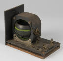
Hearwell Radio Company
Date: ca. 1915-1930
Object number: RS0780

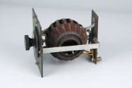
American Radio and Research Corporation
Date: circa 1921
Object number: 1998-1-0884


Date: 1890-1930
Object number: RS0508

A. H. Grebe & Company, Inc.
Date: 1925-1926
Object number: RS0063


De Forest Radio Telephone & Telegraph Company
Date: 1909
Object number: RS0171