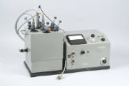
Coulter channelyzer
Datecirca 1972
Inventory Number1999-1-0090a
ClassificationCounter
Subject
Maker
Coulter Electronics, Inc.
1958-present
Cultural Region
Place of Origin
Dimensions47 × 47.2 × 32.5 cm (18 1/2 × 18 9/16 × 12 13/16 in.)
Material
DescriptionA black rectangular box with a black rubber handle on top.
The front panel has five major sections, demarcated either by black lines on the metal faceplate or an additional faceplate. The first, in the top left corner, is a circular oscilloscope screen; on the center of the screen are axes (size vs. count) on which a graph may be plotted. The second section, in the top right corner, is comprised of four small dial-style switches. Along the top half of the middle of the front panel is the third section: a black band with two adjustable two-digit indicators on either end. Between the exposed numbers is a long thin screen. The fourth section can be found beneath the third; two large dials with scales sit symmetrically on either side of the Coulter logo. The name of the object provides the boundary between the next section which runs across the bottom of the instrument; this section features one switch, one adjustable timer, one dial, and five buttons.
In a long embedded oval near the top of right side of the box is a series of switches (two) and dials (seven). Presumably these allow the user to adjust the settings for the screen. On the back of the object, not visible in the photograph, are connector ports. All knobs, dials, switches, and buttons are labeled, for example: "INTEGRATE," "UPPER CHANNEL" or "WINDOW WIDTH"; circular colored stickers applied underneath the buttons on the bottom right; a number of faded, illegible notes stuck on the bottom half of the front panel.
The front panel has five major sections, demarcated either by black lines on the metal faceplate or an additional faceplate. The first, in the top left corner, is a circular oscilloscope screen; on the center of the screen are axes (size vs. count) on which a graph may be plotted. The second section, in the top right corner, is comprised of four small dial-style switches. Along the top half of the middle of the front panel is the third section: a black band with two adjustable two-digit indicators on either end. Between the exposed numbers is a long thin screen. The fourth section can be found beneath the third; two large dials with scales sit symmetrically on either side of the Coulter logo. The name of the object provides the boundary between the next section which runs across the bottom of the instrument; this section features one switch, one adjustable timer, one dial, and five buttons.
In a long embedded oval near the top of right side of the box is a series of switches (two) and dials (seven). Presumably these allow the user to adjust the settings for the screen. On the back of the object, not visible in the photograph, are connector ports. All knobs, dials, switches, and buttons are labeled, for example: "INTEGRATE," "UPPER CHANNEL" or "WINDOW WIDTH"; circular colored stickers applied underneath the buttons on the bottom right; a number of faded, illegible notes stuck on the bottom half of the front panel.
Signedalong bottom of front panel: COULTER ELECTRONICS, INC. 590 W. 20 ST. HIALEAH, FLA 33010 / PATENTS ISSUED AND/OR PENDING
Inscribedclose to the bottom of the front panel: COULTER CHANNELYZER: For In Vitro Diagnostic Use
Curatorial RemarksIdentical to 2003-1-0104a.
FunctionThis apparatus is designed to attach to the Coulter Counter (see 2003-1-0104b) and filter its results in order to provide a more accurate estimation of the Mean Cell Value (MCV) of the solution being studied.
The apparatus works by ignoring cells that the Coulter Counter has mistakenly measured as having too great an amplitude and/or duration with respect to the electric field the cell is disrupting. These errors, which if left unchecked would lead to a mistakenly inflated Mean Cell Value (MCV), are caused by cells passing near the edge of the orifice where the electric disturbance is measured.
The apparatus works by ignoring cells that the Coulter Counter has mistakenly measured as having too great an amplitude and/or duration with respect to the electric field the cell is disrupting. These errors, which if left unchecked would lead to a mistakenly inflated Mean Cell Value (MCV), are caused by cells passing near the edge of the orifice where the electric disturbance is measured.
Historical AttributesUsed in Prof. Woodland Hastings's lab.


Luft Instruments, Inc.
Date: circa 1964
Accessories: adapter
Object number: 1996-1-0453
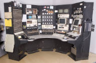
Harvard Cyclotron Laboratory
Date: 1947-2002
Object number: 2003-1-0291


CASIO Computer Company, Ltd.
Date: 1970-1980
Accessories: vinyl pouch with folded over snap cover and hanging loop; batteries
Object number: 1995-1-0012


Racal Electronics
Date: 1982
Accessories: with standard AT&T desk set, rotary dial telephone
Object number: 1998-1-0597