


Barth's gear slide rule
Datecirca 1904
Inventory Number1990-4-0011
ClassificationSlide Rule
Subject
Maker
Carl G. Barth
1860-1939
Associate Name
Frederick W. Taylor
1856-1915
Cultural Region
Place of Origin
Dimensions1.5 x 21.6 x 6.6 cm (9/16 x 8 1/2 x 2 5/8 in.)
Material
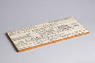
DescriptionWood rule with six slides, stacked vertically and faced with off-white paper. First, third, and sixth slides (from top to bottom) are fixed; second, fourth, and fifth slides move from left to right.
The bottom edge of the top slide printed with a scale for "Diameter of Gear," with values ranging from 1'' to 25''. Above the values from 2.5'' and above are a second set of values, the first multiplied by ten. Thus, above 2.5'' is 25''; above 3'' is 30''; and so on to the end of the scale (250'').
Facing the "Diameter of Gear" scale on the second slide are two vertical arrows. One, approximately one-quarter of the way across the slide from left to right, is labeled, "For Diameters Above 25'' Use This Arrow." The second arrow, close to the right end of the slide, is labeled "For Diameters Up to 25'' Use This Arrow." On the bottom edge of the same (second) slide is printed a scale for "Number of Teeth in Gear," carrying values descending from 300 to 12.
Three scales are printed on the third slide. Along the top and bottom edges are identical scales for "Diametrical Pitch," or "Number of Teeth per Inch [of Diameter]," with values descending from 12 to .5. In the center, with hash marks extending to both top and bottom edges, is "Circular Pitch," with values ranging from 1/4'' to 6''.
The fourth slide is also printed with three scales. Along the top edge are two scales, stacked vertically, for "Number of Teeth in Gear." The top scale, for "15° Involute System," carries values descending from 300 to 12. The second scale, for "20° Involute System," likewise carries values descending from 300 to 12. Printed along the bottom edge of the same (fourth) slide is a scale for "Face of Gear Divided by Circular Pitch," carrying values from 1 to 10.
Printed on the top edge of the fifth slide is a scale for "Permissible Stress on Material at 0 Velocity, in Pounds per Square Inch," carrying values descending from 50,000 to 1,000. Along the bottom edge of the same slide is a scale for "Circumferential Velocity of Gear, in Feet Per Minute," with values descending from 5,000' to 0.
The sixth, or bottom, slide, has a scale for "Tangential Load on Gear, in Pounds," with values ranging from 100 to 50,000, printed along its top edge.
The bottom edge of the top slide printed with a scale for "Diameter of Gear," with values ranging from 1'' to 25''. Above the values from 2.5'' and above are a second set of values, the first multiplied by ten. Thus, above 2.5'' is 25''; above 3'' is 30''; and so on to the end of the scale (250'').
Facing the "Diameter of Gear" scale on the second slide are two vertical arrows. One, approximately one-quarter of the way across the slide from left to right, is labeled, "For Diameters Above 25'' Use This Arrow." The second arrow, close to the right end of the slide, is labeled "For Diameters Up to 25'' Use This Arrow." On the bottom edge of the same (second) slide is printed a scale for "Number of Teeth in Gear," carrying values descending from 300 to 12.
Three scales are printed on the third slide. Along the top and bottom edges are identical scales for "Diametrical Pitch," or "Number of Teeth per Inch [of Diameter]," with values descending from 12 to .5. In the center, with hash marks extending to both top and bottom edges, is "Circular Pitch," with values ranging from 1/4'' to 6''.
The fourth slide is also printed with three scales. Along the top edge are two scales, stacked vertically, for "Number of Teeth in Gear." The top scale, for "15° Involute System," carries values descending from 300 to 12. The second scale, for "20° Involute System," likewise carries values descending from 300 to 12. Printed along the bottom edge of the same (fourth) slide is a scale for "Face of Gear Divided by Circular Pitch," carrying values from 1 to 10.
Printed on the top edge of the fifth slide is a scale for "Permissible Stress on Material at 0 Velocity, in Pounds per Square Inch," carrying values descending from 50,000 to 1,000. Along the bottom edge of the same slide is a scale for "Circumferential Velocity of Gear, in Feet Per Minute," with values descending from 5,000' to 0.
The sixth, or bottom, slide, has a scale for "Tangential Load on Gear, in Pounds," with values ranging from 100 to 50,000, printed along its top edge.
Signedface, 4th slide, right: Strength of Spur Gears / According to Wilpred [sic] Lewis. / Carl G. Barth / Patent Applied for.
Inscribedback, pencilled in center: B
Curatorial Remarksprobably dated and patented at the same time as 1990-4-12 probably made in the same place as 1990-3-2 (notice the date);
Records indicate that Barth was working in Philadelphia in 1904;
Nearly identical to, though of slightly different dimensions than, 1990-4-0012;
Similar in function to circular gear slide rules dated 1902, see 1990-4-0033, 1990-5-0003;
FunctionFor calculating the strength (in load in pounds) of spur gears.
The user first determines the pitch of the gear in question by moving the second slide left or right so that the appropriate arrow (right-hand arrow for diameters up to 25''; left-hand arrow for diameters over 25'') points to the diameter of the gear (top slide). The diametrical pitch of the gear is that value on the third slide's top scale coinciding with the number of teeth in the gear (second slide, bottom scale). If the user knows the circular pitch value of the gear, he can skip this step.
The user then moves the fourth slide left or right to set the number of teeth of the gear (top scale, choosing between the scales for "15° Involute System" and "20° Involute System," as applicable) to coincide with the pitch of the gear (third slide, either diametrical or circular pitch as appropriate).
Then, keeping the fourth slide in place, he moves the fifth slide to left or right in order to align the permissible static stress on the material (fifth slide, top scale) with the face of the gear (fourth slide, bottom scale).
Now, keeping both the fourth and fifth slides in place, he locates the circumferential velocity of the gear on the fifth slide's bottom scale. The coincident value on the "Tangential Load" scale (sixth slide) indicates the strength of the gear.
This slide rule derives from a formula published by Wilfred Lewis in 1893. See "Primary Sources" for citation.
Barth also produced circular gear slide rules.
The user first determines the pitch of the gear in question by moving the second slide left or right so that the appropriate arrow (right-hand arrow for diameters up to 25''; left-hand arrow for diameters over 25'') points to the diameter of the gear (top slide). The diametrical pitch of the gear is that value on the third slide's top scale coinciding with the number of teeth in the gear (second slide, bottom scale). If the user knows the circular pitch value of the gear, he can skip this step.
The user then moves the fourth slide left or right to set the number of teeth of the gear (top scale, choosing between the scales for "15° Involute System" and "20° Involute System," as applicable) to coincide with the pitch of the gear (third slide, either diametrical or circular pitch as appropriate).
Then, keeping the fourth slide in place, he moves the fifth slide to left or right in order to align the permissible static stress on the material (fifth slide, top scale) with the face of the gear (fourth slide, bottom scale).
Now, keeping both the fourth and fifth slides in place, he locates the circumferential velocity of the gear on the fifth slide's bottom scale. The coincident value on the "Tangential Load" scale (sixth slide) indicates the strength of the gear.
This slide rule derives from a formula published by Wilfred Lewis in 1893. See "Primary Sources" for citation.
Barth also produced circular gear slide rules.
ProvenanceThe papers and slide rules of Carl G. Barth and his son, J. Christian Barth, were transferred to the Baker Library of the Harvard Business School by J. Christian Barth in 1961.
The slide rules were transferred from Harvard Business School to the Collection of Historical Instruments in 1980.
Historical AttributesThis is part of a set of slide rules for machine shops designed by Carl G. Barth under Frederick Winslow Taylor's system of scientific management. Given the characteristics of a particular machine and a depth of cut, for example, a shop manager could quickly calculate the most efficient speed and feed settings using one of Barth's speed and feed slide rules. Other objects in the collection include slide rules for helical springs, belts, and gears, as well as jigs for making slide rules.




Carl G. Barth
Date: copyright 1902
Accessories: storage box; instruction booklet in instrument file
Object number: 1990-4-0033

Carl G. Barth
Date: copyright 1902
Accessories: storage box; instruction booklet in instrument file
Object number: 1990-5-0003


Pickett & Eckel, Inc.
Date: circa 1951
Accessories: brown leather case with table of equivalents
Object number: 2004-1-0341


